For one of my classes I was given a toy robot to model and simulate. I took some time lapse video and made this compilation of it’s creation. Enjoy!
Sunday, March 6, 2011

Tuesday, January 25, 2011
It moves!

Motor Mount Shims
So in order to make motor mount shims (which was required due to motor adapter geometry, and unplanned design) I found a piece of scrap composite board. After an attempt to cut it on the vertical band saw (blade was shot.) I moved to a manual saw blade, then a very helpful fellow who works in this shop pointed out a skillsaw I could use. I clamped it to the table, and made quick work of the board, to make 3 simple blocks to shim the motors with.The last picture shows how it will shim the motor mount.


With some more milling of the motor mount (which is tedious to remove from the nema23 motor by the way...) Holes were located and drilled through the shim, the motor mount, and the frame. It's obvious to see how i almost had serious clearance issues with these motor mount bolts.


Aside from bending the motor mount by being inattentive, I got it all attached to the ballscrew, and frame. I hooked it up to the computer, and ran some simple tests on mach 3. The same helpful shop fellow recognized that the bolts holding the ballscrew in place were sort of loose (which they are.) The issue is I used some readily available fasteners that don't quite fit right, and can't be completely tightened, so i need to buy some socket head cap screws.
Here is a video of the ballscrew moving via mach 3 commands.
Motor mounts, and frame progress.


 After bringing all the components back to the senior project lab in school, and getting permission from various school officials to work on this project. I laid everything out. I loosely attached all the components to their mounting boards, and semi-permanently drilled drywall screws to attach the mounting boards to the 2x4 frames. This required a great deal of pre-drilling to ensure nothing cracked.
Using scrap 2x4s i machined some blocks to affix the y to the x axis. The
manner in which i assemble everything requires some careful thought. I put this on the back-burner to see if i want to make a solid aluminum plate design instead. You can see how the y axis will rest on the x when complete

These are some motors mounts i machined out of some scrap steel. One side is not flat, so it could be an alignment issue in the future, but it was a good exercise none-the-less.

Learning Fanuc Robots

Last term I spent some time taking MFG 453 Automation and Robotics, I learned a great deal in that class as well as how to operate, and program fanuc robots. I'm not going to go into the details but here are two project videos I did with my group. Along with various pictures:
http://www.youtube.com/watch?v=OgfUooDao10 (Final project - HD available)
http://www.youtube.com/watch?v=PkJC5Yk7Tk0 (First project)
Cool Stuff!


Nerf Gun


I'm not a crazy fan of nerf, but it was fun while i was a kid. In any event my college wing has gone nuts about it. So I figured I'd join in the fun - but in my own special way ;D
I started by working on the firing mechanism, and propulsion system. As I knew that would make or break the final part. I decided to a complete backyard engineering design due to limited time (and I was confident I could do it.) I bought a package of nerf rounds for under 10$, and 30$ worth of PVC (I have a lot left over now.) I als
o bought a nice sized 7$ spring from Diamond hardware store, and a few random other fastener pieces etc. Probably spent a total of 8 hours making this thing. Used a Dremel, power drill, pipe cutter, superglue, and some time to come out with this:


Performance:
Muzzle Velocity : (Unknown)
Effective range: 0-130 feet
Max Range: 150-200 feet
These are merely approximations, but it easily has 3 times the range of a traditional nerf gun. I believe if I took the time to tweak it some more, and make custom rounds it would increase performance further.
Return to blogging
Overview
After what has been several months since my last post i figure I should update this. I'm going to cover just a few personal projects, and cnc updates in a somewhat chronological order. There is a lot i did on my internship, which i cannot disclose due to a proprietary nature. Rest assured it was cool stuff! Thanks pcc!Laptop Fan Repair
To kick things off. I'll cover a simple laptop repair I
performed on my dad's laptop. I normally wouldn't post this as I find computer construction quite trivial, and just about anyone can build a computer these days. I can't count how many PC's I've built. I posted this because it's a laptop. Normally I don't touch them due to the ability to void a warranty.
In this case the laptop is so old there is no warranty to void anymore. My dad thought his computer was getting slow. We did a burn and format, and still noted slow performance. This is when I suspected hardware. I discovered the CPU fan wasn't spinning (or i surmised as there was no airflow or sound.) My dad also confirmed this as it was making very bad sounds, then stopped. I dug up a service manual from much scouring of the internet on how to dissasemble this beast.
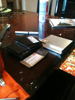
What you see below is the major components removed on the left, and the remaining motherboard. After finding the interesting heat/pipe system they had installed i successfully removed the fan, after bending many plastic parts per-the manual's instructions. I looked up the part number, and sourced it from HP for about 50$. Found it on ebay for 11$ new. Purchased and installed it after a week's wait.
I then configured the bios to leave the fan explicitly on, instead of throttling per cpu usage. Computer ran like a champ after that!

Wood Frame construction.

I've since moved back to OIT and moved the machine here too. Between my internship at Pcc and school I've been too busy to update this blog.
Back to the meat. Since my last update, i built 3 wood frames while at home due to lack of access/time to properly machine the proposed 80/20 aluminum extruded frame. This involved using a skillsaw to fabricate 2 saw horses, then cutting up about 8x8' 2x4s to various lengths. Utilizing drywall 2-1/2" screws I fabricated these wood frames. Each wood frame is used for each axis in it's entirety. I then located and installed the rails, and ballscrews to each of these wood axis frames. I used some leftover white shelving made 3/4" plywood and or particleboard depending on the axis. I utilized the plywood for the Z-axis for strength.
Back to the meat.
Since my last update, i built 3 wood frames while at home due to lack of access/time to properly machine the proposed 80/20 aluminum extruded frame. This involved using a skillsaw to fabricate 2 saw horses, then cutting up about 8x8' 2x4s to various lengths. Utilizing drywall 2-1/2" screws I fabricated these wood frames. Each wood frame is used for each axis in it's entirety. I then located and installed the rails, and ballscrews to each of these wood axis frames. I used some leftover white shelving made 3/4" plywood and or particleboard depending on the axis. I utilized the plywood for the Z-axis for strength.The project had been sitting around due to my internship so long i had the itch to get something done, and with no access to machining equipment settled to make a wood frame first, with the intention of converting to a metal frame later. I thirst for more CNC experience out of the class, even if i'm only cutting wood, plastic, or wax.
Going through this process taught me the importance of locating individual components, i'm sure it will become even more important when made in metal. I wish I had modeled the wood frame completely, instead of deriving data from the 80/20 model. Given that I had less than a week to work on this before I went back to school (after internship.) I was pleased with the result. My good friend Bryan helped me substantially with this. I also purchased a 2.5 HP router for around 100$ at Lowes to just have something to start with.
[Pictures taken 9/22/10]


Saturday, June 5, 2010
CNC resumes!
Machine Move, Ballscrew setup

I'm back! I have been so busy with school, internships, work, that until now I've been full up to my ears with stuff! I'm interning for a major northwest manufacturer making metal parts.
Troy's brother has a great shop, and is kind enough to let us work there on our CNC project. I moved all the components out of my room to there! What a relief! My room no longer smells like gear grease!
So at this stage the controller board is working with the 3 stepper motors, and the computer. The same day that we moved the stuff there we bought some shelves and put them in place to keep all the equipment. We spent that time building installing the shelves.
Another week we came in and worked on assembling the ballscrews. They were a really tight fit, the ballscrews were purchased on ebay custom cut to our size. So we were saving money by doing this. Unfortunately, the ballscrew blocks, that hold the bearings were not sized perfectly, they were an interference fit. So we tried heating the blocks with a torch lightly. We found that didn't work that well at all. What did work was forcing them on with force, and properly aligned pressure. So that is what we did.


We had to bore out the insides of the motor mounts as they didn't quite fit on the s
haft, Troy was able to quickly take care of that on his harbor freight lathe. (Paying attention not to break a v-belt.)

------
Motor Wiring

Today grant came to work on the machine with us too. He rewired the motors to utilize RJ-45 we have concerns that the wires are not thick enough to carry the current. We looked it up, they have a max spec based on 24AWG of 3.5 AMPS per individual strand. Our motors in unipolar mode will be running at 2 Amps. Our voltage is something like 24 volts? not sure, i'll have to check that later. I'm concerned
that the limiting factor is not just current but power over the line. So we will have to double check that
later.
Troy traded some equipment and acquired a ton of aluminum extrusion, that should work great for a frame. This means we will have to source some connector plates, and design them as well.

Troy quickly worked up a new control board mounting strategy with the motherboard mounting kit I found. He cut, and drill/tapped aluminum scrap to make the mounts. He also he-manned one of the brass screws, and broke it off in the hole, so he had to re-drill and tap to fix it.
If we are good we will need to:
* Purchase Female RJ45 connectors so we ca
n easily disconnect the motors from the control board. (If rj-45 is ok for our CNC motor power)
* Consider shielding options for the motor wires.
* Finish mounting the control board
* Model the frame again with the new extrusions troy got.
* Install limit switches
* Bring more RJ-45 cable for limit switches.
* Explore spindle options
These are the ends, that would be nice to have rj-45 connectors on them. It is easy to pull out a motor's wires at the control board. We also cut and drilled some simple aluminum angle iron to act as a heatsink on the drives. A quick run to the store and we had the right fasteners.

Wednesday, November 18, 2009
CNC Plasma, and potential laser cutting/plasma projects
 Cool Stuff in Numerical Control Programming Class
I've been assigned to come up with some maintenance documentation for the Plasma CNC we have at our school. It is obvious that it isn't used much. The documentation for the torchmate 2 system is nicely done. I believe it was a previous senior project from a kit, and it's obvious the students did a wonderful job setting it up.
Today, I had the opportunity to start the machine up (after carefully reading the documentation) and jog the x and y axis around. I'd like to measure the kerf sometime soon to document that.

I eventually will need to come up with a sample part that my professor will be able to easily demo to prospective students. So i'm trying to come up with ideas for that. Here are some neat links with great ideas and source files:
http://www.cnczone.com/forums/showthread.php?t=5276
http://www.cnczone.com/forums/showthread.php?t=19346
In my research about the CNC plasma cutters
 I've stumbled across a wealth of resources that I wish I had time to dive into right now.
http://www.cncinformation.com/advanced-robotic-tech-cnc-plasma-cutter-videos/
which has a variety of videos talking about CNC plasma cutting.
I signed up for a yahoo group where I was able to find a majority of these resources from:
http://tech.groups.yahoo.com/group/plasmacutting/

Monday, November 9, 2009
Getting involved
Whether it is a detrimental thing or not I'm getting involved in two more clubs at my school.
I've been researching high altitude balloons for taking atmospheric pictures like the one below(100,000 feet.) I am very excited about it. I am timid to commit too much time though as I have plenty of schoolwork and other projects going on at the same time. I just made a personal decision not to let good opportunities pass me by. "Reach for the stars" so to speak.

Image from http://www.natrium42.com/halo/flight2/#hardware
Here is some of the fruits of my research:
So for now I'm just going to try and stay on top of things, as they just keep piling up, and i keep knocking em down at about the same rate. Kind of a good and bad thing. *shrug* at least it's progress. Onward!
- Mars Reach
- Society of Manufacturing Engineers
I've been researching high altitude balloons for taking atmospheric pictures like the one below(100,000 feet.) I am very excited about it. I am timid to commit too much time though as I have plenty of schoolwork and other projects going on at the same time. I just made a personal decision not to let good opportunities pass me by. "Reach for the stars" so to speak.

Image from http://www.natrium42.com/halo/flight2/#hardware
Here is some of the fruits of my research:
- http://vpizza.org/~jmeehan/balloon/
- http://www.universetoday.com/2006/01/20/satellites-on-a-budget-high-altitude-balloons/
- http://hackaday.com/2009/09/19/high-altitude-balloons/
- http://www.natrium42.com/halo/flight2/#hardware
- http://www.arhab.org/
So for now I'm just going to try and stay on top of things, as they just keep piling up, and i keep knocking em down at about the same rate. Kind of a good and bad thing. *shrug* at least it's progress. Onward!
Subscribe to:
Posts (Atom)
